Individually addressed RGB LED strip, “before it was cool”.
That’s one of my first projects. And first projects usually features LEDs. This one is all about LEDs!
Why not buy off eBay/Adafruit/SparkFun?
The “why” to this project is not justified anymore as you can buy those RGB LED strips pretty cheap in about every hobby electronic shops. But a couple years ago, I started playing with the “original” RGB strips, where all the LEDs would light up the same color, like those. You could not find individually addressable LED strips at a decent price (or even not at all!).
SMD RGB LEDs like the 5050 were common though. A small IC started to become popular too, the WS2801. The WS2801 is both the ancestor and the more complex version of the WS2811 that is on today’s RGB strips. It features three 8-bit PWM current sources (for Red, Green and Blue) per chip. The maximum intensity of each current source can be set by a resistor, then the duty cycle varies the average current between 0 and Imax. The WS2811 contains three 8-bit PWM fixed current sources (0 to 18.5mA), but has only 8 pin, compared to the 14 of its predecessor. Both of them are controlled via a serial interface that is cascaded to the next chip, but the WS2811 does not use a clock signal, requiring precise timing of the input signal.
The PCB
I wanted to be able to chain as many LEDs as possible, but still use Seeedstudio’s Fusion PCB service. I also wanted the strip to be thin enough to fit on most of my projects, that’s why I chose to have multiple 50x10mm-ish PCBs (10 for $10).
I managed to fit 4 LEDs and 4 WS2801’s on the backside together with decoupling capacitors and current setting resistors by using microscopic 0402-sized resistors. Those were the smallest components I ever hand soldered at this time, but I was confident.
 Top
Top
 Bottom
As you can see, on one extremity of the board, you have +5V, GND and the clock and data input to the first IC and on the opposite side, the same supply rails and the cascaded output for the data and clock of the 4th chip, ready to be hooked up to the next board.
Note that the PCB traces for the power supply are pretty thin and I wouldn’t put more than 1A in them. At full brightness it corresponds to 16 LEDs or 4 boards before having to bring another wire from the power supply.
Ordering the components
The PCBs were ordered from Seeedstudio and received 3 weeks later (delivered in France). I was surprised to receive 21 boards, instead of the 10 ordered, and at this day I still don’t know why!
This meant more LEDs, so I happily bought 100 5050 RGB LEDs from Adafruit. 100 WS2801 were ordered on alibaba.com. The passives (capacitors and resistors) were bought in bulk (100pcs each) on eBay.
Soldering
Alright… At this point I think I was too excited about this project to notice that I was seriously underestimating the time and patience it would take to solder 80 LEDs, 80 SOIC14 chips, 80 capacitors and two hundred and forty (240) 0402, ridiculously small resistors on 20 different PCBs! Nonetheless, I started soldering and managed to finish about 10 of those in 8 hours, before developing an allergy to soldering irons.
A bit of Arduino coding, and this was the result:
It worked great! And I was happy, but I had 10 more boards left in a box, and they stayed there for a while.
The forgotten boards
After a while, I built a quadcopter from scratch with 4 friends for the equivalent to a senior design, but 2 years after high school and we absolutely wanted to pimp it and add LEDs under the arms. We used the SMD oven and solder paste dispensers from our university to complete the 10 left boards.
Pictures? Here you go:

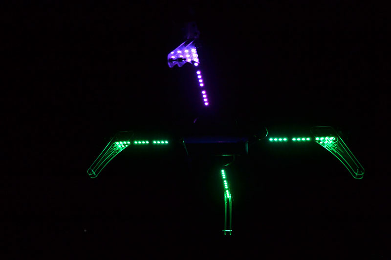

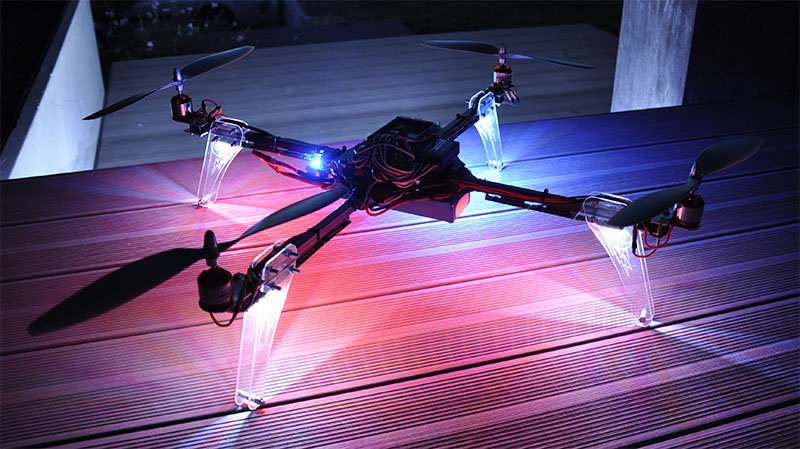
Nobody called the police about a UFO… Yet!