This is my first real project and it’s awesome, because it solves Rubik’s Cubes!
Rubik’s Cube robot solver
For our high school senior project, each one of us had to design and build a system using what we learned in electronics and mechanics. With a friend, we settled to build a Rubik’s Cube robot solver.
[vimeo 33931082 w=600 h=450]
PPE Rubik’s Cube – vidéo du prototype from Valentin TRIMAILLE on Vimeo.
The robot
It is a pretty simple piece of hardware. The robot has two homemade claws actuated by one servo each (open and close). We control the rotation of the claws with two other servos (rotate a face or the whole cube).
The fingers of the claw are made out of two pieces of sheet metal bent. We cut and glued plastic gears to each finger. Finally, the servo is screwed to one of the gear. We added some rubber (hatched part) to increase the grip of the cube.
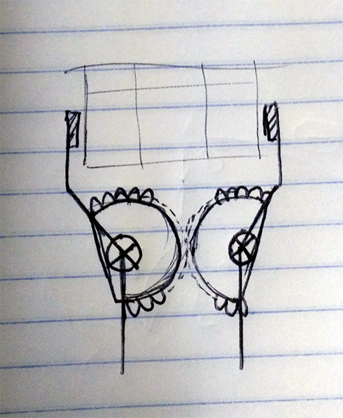
As you can see in the video, the claws are mounted to a wooden box at an angle of 90° of each other so that one claw can hold the cube while the other rotates the face. The “wrist” joint is capable of rotating from 0° to 180°. Because it was our first design, the claws are not sturdy enough to reliably solve the cube, so we have to help it from time to time by moving the cube a bit. But well, for a first, it’s not that bad!
Solving algorithm
Given the duration of the project (3 months), we quickly abandoned the idea of writing a Rubik’s Cube solver from scratch! I contacted Herbert Kociemba, he was working on God’s Algorithm and ended up proving the same year that the maximum number of required moves to solve any cube, God’s Number was 20. Anyway, he ended up kindly sending me his code, with his encouragement.
At this point, I had a program taking the configuration of a cube and outputting a list of less than 20 moves that would solve the cube. That’s perfect, right? 20 is the lowest you can get, right? And it doesn’t take so long to compute, right..? Well, it actually took 30 minutes to solve some cubes on my poor Pentium 4… Fortunately, a quick tweak, and the solver was looking for 25 moves or less. The hardest cube was solved in under a minute, good enough.
Clean interface
The only problem left with the solver was it’s user-unfriendliness. This is a solved cube:
         Gr Gr Gr
         Gr Gr Gr
         Gr Gr Gr
Re Re Re Wh Wh Wh Or Or Or Ye Ye Ye
Re Re Re Wh Wh Wh Or Or Or Ye Ye Ye
Re Re Re Wh Wh Wh Or Or Or Ye Ye Ye
         Bl Bl Bl
         Bl Bl Bl
         Bl Bl Bl
This is the input string for the solver:
L:RRRRRRRRR R:OOOOOOOOO U:GGGGGGGGG D:BBBBBBBBB F:WWWWWWWWW B:YYYYYYYYY
This method asks a lot to a first-time user.
In which direction the cube should be held: this face facing up or down?
In which order the tiles have to be entered: top-left to bottom-right, in a circle, …?
That’s why we decided to create GUI with two isometric views of the cube and a color palette – and also because it’s wayyy cooler!
I used some C++ and the framework Qt to program it. The user selects the color in the top palette and applies the color by clicking on a tile. When the cube is completely colored with 9 tiles for each color, the Solve! button is enabled. Clicking on it translates the pretty colors into the repulsive input string, feeds it to the modified solving algorithm and waits for the solution.
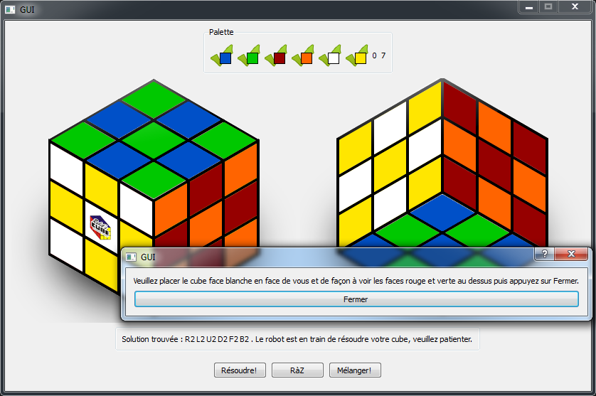
Solution found: R2 L2 U2 D2 F2 B2.
The sequence of moves is written to a file and the LabJack program is started.
HW/SW interface
Our professors gave us a LabJack U12 to interface our hardware with our software. It is basically a USB I/O expansion for computers. You can toggle and read digital or analog I/O from a C++ API, which is pretty nifty. Unfortunately this device was to slow to generate the PWM signal our hobby servos needed. At this time, I’ve been knowing Arduino for a couple of months and thought I could replace the LabJack with one but our professors insisted on keeping the LabJack U12 so we simply added an Arduino in the middle. Not the best but it still worked.
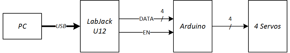
4 digital outputs were used to communicate a 4-bit code to the Arduino. The EN output was set high when the DATA lines could be read. The Arduino then used a table to find the corresponding action:
| Code | Movement |
| 0000 0001 0010 0011 |
Close right Open right Close left Open left |
| 0100 0101 0110 0111 1000 1001 |
Right to 0° Right to 90° Right to 180° Left to 0° Left to 90° Left to 180° |
LabJack program
This small program is indeed used to communicate with the robot through the LabJack U12, but not only. The sequence of cube movements (i.e. U2 means rotate the top face of 180°) must be decomposed into robot movements like “open left claw”, “rotate left to 0°”, “close left claw”, “rotate claw to 180°” for example (this rotates the face on the left of 180°). It must also keep track of the cube’s orientation as the robot will rotate the cube to access other faces.
The list of robot movements is then sent one by one to the Arduino, effectively solving a Rubik’s Cube!