PCB design
The goal of this project is to design three PCBs in Eagle CAD that stacks together to form the watch. No other material is needed to attach straps, protect the components or activate the watch (like a button). Compared to the DaTajm, I opted for embedding the LEDs inside as well, for protection. The three PCBs have different roles and components:
- Bottom: 12 red LEDs + 4 orange LEDs, positive pad for the battery.
- Middle: Spacer, with embedded current limiting resistors. Connects the top PCB to the LEDs.
- Top: Main board containing the MCU, crystal, programming header and negative pad for the battery. Touch sensor on the other side.
I chose a small form factor as I have a small wrist, and big bulky wristwatches look, well… Big and bulky on my wrist. The watch a disk 30mm in diameter with extensions in each corner for the four screws. I extended the watch to add fixations for a NATO-style 20mm wristband.
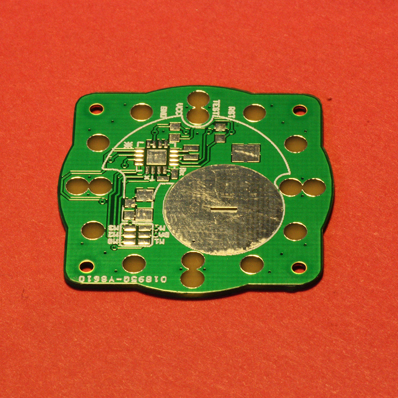
The top PCB
We’ll start from the top as it is the most complex PCB.
The LEDs must shine through it, so I tested with PCBs from old projects (1.6mm thick) and a single LED is visible through the bare substrate material the PCB is built onto (copper, silkscreen and solder resist removed). I decided to create 16 disks of bare PCB where the LEDs would be, to let the light shine through and not to drill holes as Seeedstudio’s Fusion PCB service proposed 0.8mm thick PCBs for the same price.
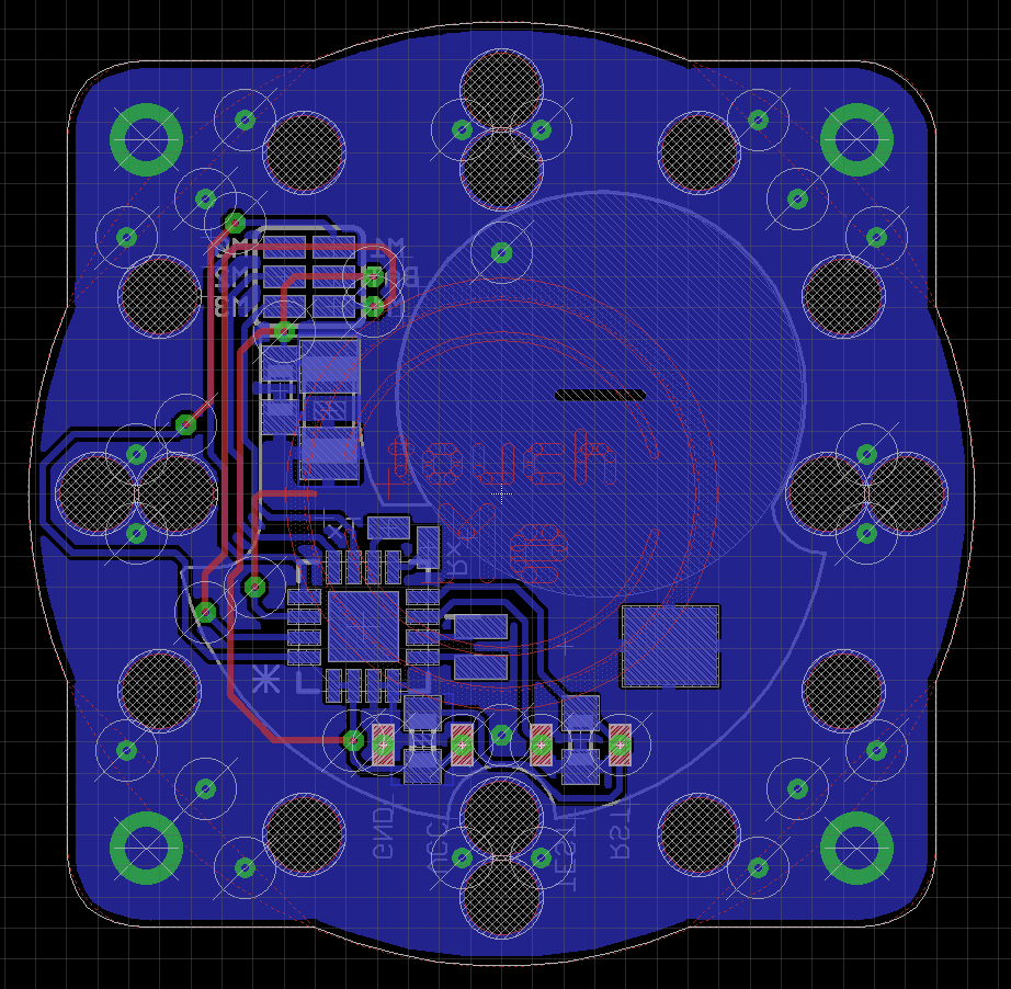
The components would go on the underside of the PCB, while leaving enough room for the coin cell. A big pad is left exposed to become the negative connector for the battery. An array of 2×3 small pads are used to connect the LEDs and the positive side of the coin cell to the bottom PCB through the middle one, just by contact.
The top side has an isolated disk of copper in the middle with “touch me” engraved in it, this is the touch sensor. A wire connects directly the disk to a pin of the MCU on the other side. I added 4 small pads, almost unnoticeable at a 0.1″ pitch allowing me to load a new program without opening the watch. I designed in Photoshop a honeycomb pattern with different kind of filling to be printed as the silkscreen for decoration. It hides the programming header and the few tracks of the top.
Finally, four big holes are added to let the screws traverse and screw into the bottom PCB.
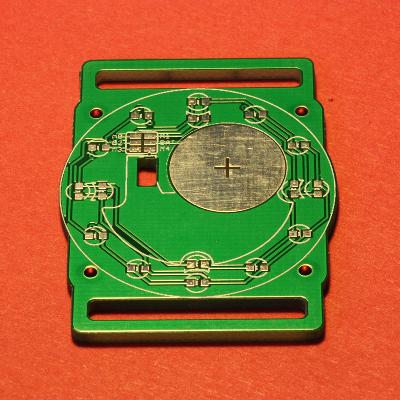
The bottom PCB
This PCB is much simpler. The 12 red LEDs are laid in a circle, representing the 12 hours of an analog clock and the 4 orange ones are positioned just next to the 12, 3, 6 and 9 hours. The LEDs are Charlieplexed and only uses 5 pins for 16 LEDs (up to 20 with 5 GPIO).

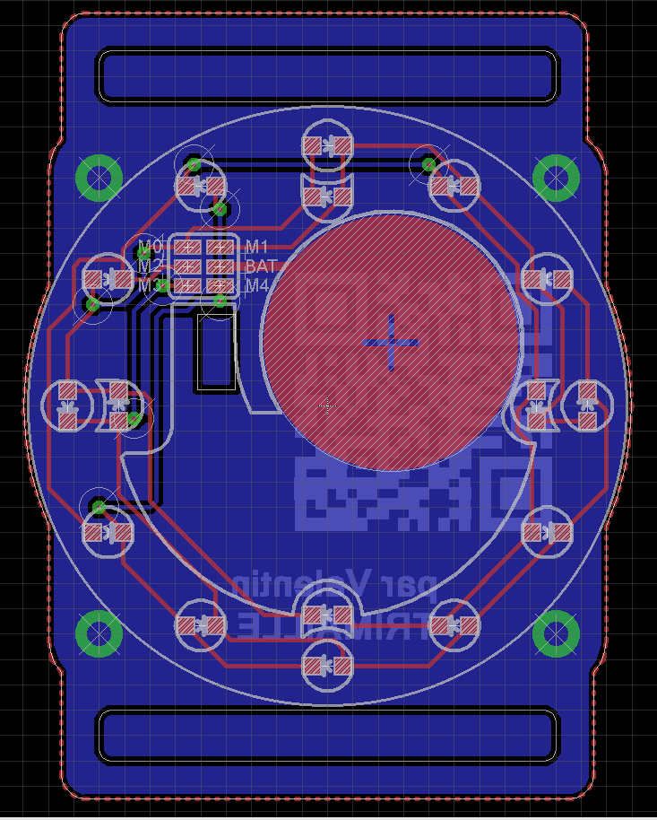
You can see the brackets for the wristband. A rectangular hole is cut out next to the 6 pads connector to let the 2.2µF capacitor of the top PCB fit as it is thicker than 1.60mm (the height of the middle PCB). Next to it, the big positive pad of the battery is also an exposed disk of copper.
I added a QRCode linking to an URL I can change (currently my LinkedIn profile) on the silkscreen of the bottom side. The silkscreen on the top side represents the cutouts in the middle PCB, showing where I have room for components.
The four screw holes at the corners are slightly smaller than the diameter of the screw I bought. The plating in the hole is soft and the screws will easily form threads in it.
The middle PCB
This is basically just a spacer for the battery and the components. Holes are cut for the LEDs and the battery is hold in place in a cutout disk.
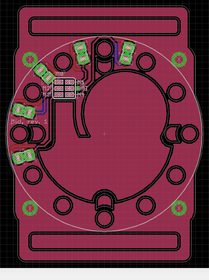
You can see on the top left corner, 5 resistor embedded into the PCB. 5 rectangular cutouts holds the resistors and castellated holes on each extremity allow for soldering the resistor pads.

The 6 pads on the top side are connected to the 6 pads on the bottom side through the resistors, except for the battery positive terminal of course.
The cutouts for the LEDs are isolating one LED from the light of the others. The thickness of the walls between red and orange LEDs is very small, around 0.7mm. It was out of tolerance of the PCB service, but ended up very clean

Fail of the middle PCB
I’m a better electrical engineer than a mechanical one, and this is where I learn that my design was crazy and will never work… At least the 6 pads connector won’t, the rest is fine, really.
The connection was very poor and unreliable between the PCBs. I had to solder 6 magnet wires from the top to the middle and 6 others from the middle to the bottom. Now the watch is full of tiny wires, and I hope I’ll never have to open it again, because it’s a pain to close!
Thanks for sharing! It looks great.