The software
Software side, the important thing to save a maximum of juice, is to sleep as much as you can. It’s kind of similar to engineering school actually! Jokes aside, let’s talk about how the watch does it.
Periodic check and RTC
The RTC crystal is linked to the ACLK clock source (Auxiliary CLocK). This clock source stays active with the crystal’s excitation circuit until LPM3 (Low Power Mode 3). LPM3 is the lowest LPM with a clock running. If you are in LPM4, only a physical interrupt can wake the MCU up.
I configured the watchdog timer to overflow and interrupt the LPM3 every 250ms. During this interrupt, the touch sensor is checked for input and the state machine is run. Oh, and we also increment the time variable (counting quarter of seconds). If no press occurred, we go back to sleep in LPM3.
This means that if you press the touch sensor for less than 200ms chances are that your press has a chance to be unnoticed. But it is the price to pay for a greater battery life.
The state machine
State machines are really awesome to manage the tasks of any microcontroller, especially in response to user input. You can define states and transition between those states on arbitrary conditions: time, interrupt, state of an internal variable, … It is also very clean coding using an enumeration for the states and a switch/case to evolve the state machine according to which state is active.
Here is the state machine of the watch:
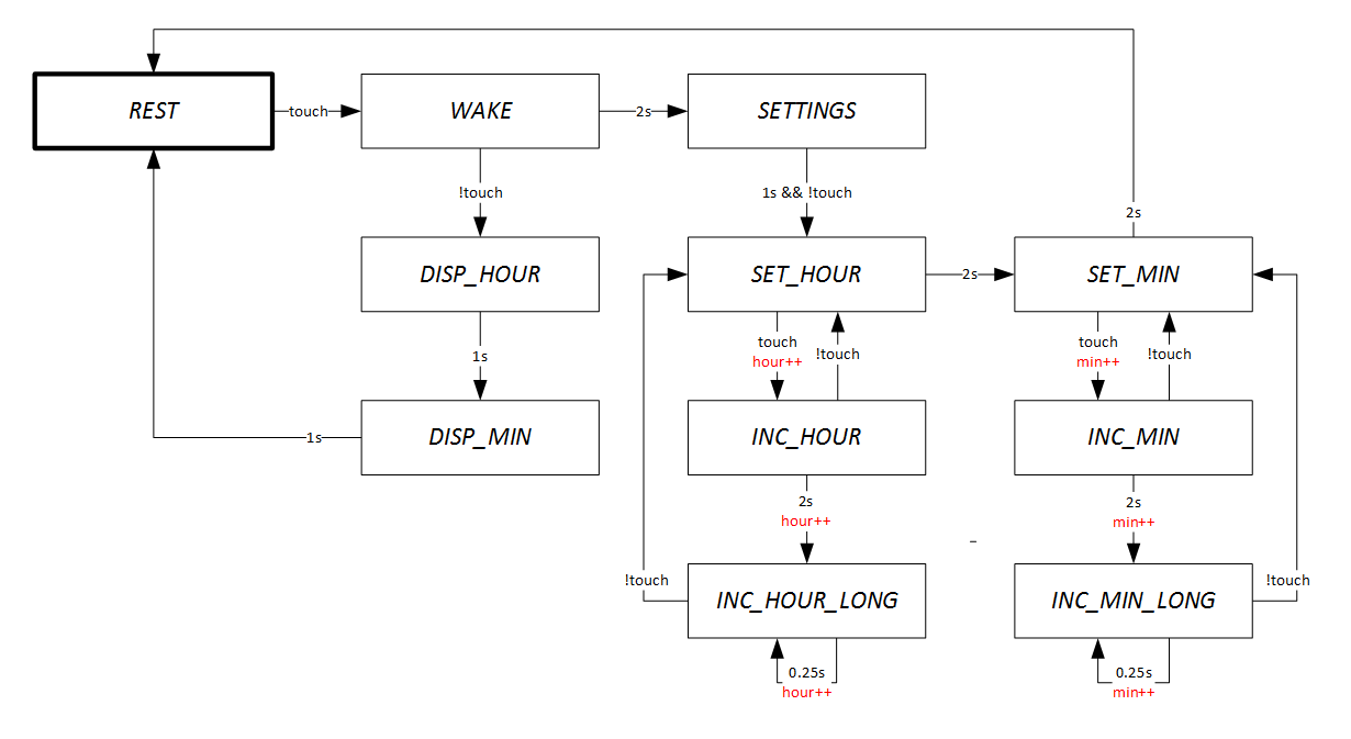
Starting in the REST state, we wake up every 250ms. If a touch is detected we transition to WAKE which differentiate a short press from a long press (over 2s). A short press displays hours (DISP_HOUR) and then minutes (DISP_MIN) for 1s each before going back to REST.
A long press flashes the LEDs while entering the SETTINGS state. You can then increment the hour by pressing the touch sensor (SET_HOUR & INC_HOUR). A long press continuously increments the hour (INC_HOUR_LONG). After a timeout of 2 seconds without activity, you can do the same with the minutes (SET_MIN, INC_MIN & INC_MIN_LONG).Sensing the capacitive touch button
Monitoring the touch sensor is done by using the internal excitation circuits. It uses the parasite capacitance of the copper disk to oscillate a RC circuit. When you approach your finger, this capacitance changes, affecting the natural frequency of the oscillator. If you can measure the number of oscillations in a fixed time frame, you can infer the change in capacitance, and check for user input.
All this is provided in a nice library from TI, the CapSense library with tons of resources, Application Notes and reference designs.
A last word
I’m very proud of this watch while a lot of it could use a serious upgrade.
First of all, the connections between the top and the bottom layer has to be redone. Every time I change the coin cell, I cringe just thinking that I’ll have to close the watch again.
Next, the battery life is now around 30 days of normal use. The average current consumption is around 35-40µA without user input. Comparing this with the 1µA application note, and considering I do a bit more of computation, have a RTC and wake up 4 times as often, I should stille be able to lower the current consumption under 7µA average. I still haven’t troubleshooted the cause of the overconsumption, but I can reproduce the problem with a very simple firmware using the RTC and the CapSense library. Apparently, the MCU doesn’t fully go to LPM3, maybe only LPM2, or LPM0.
Finally, for version 2, I’ll probably get rid of the coin cell. 2 supercaps at 200mF each and a tiny solar array like the CPC1822 should be enough to keep the watch running with only 4 hours of sunlight a day! Cool right? But this is for a 7µA average power consumption…
Thanks for sharing! It looks great.